
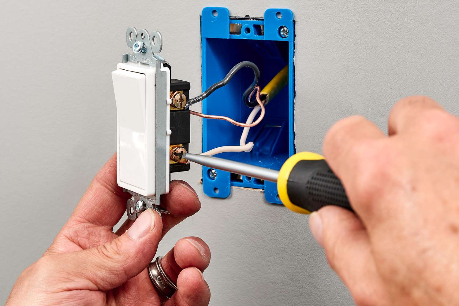
Learning how to wire a light switch can help you handle a common home repair, but electrical work should never become a guessing game. A basic wall switch may have only two or three connections, yet one loose or misplaced wire can cause electric shock, overheating, arcing, or fire.
This guide explains how a typical single-pole light switch works and how to replace one safely. It also covers wire colors, line and load connections, grounding, older switch loops, three-way switches, dimmers, smart switches, common mistakes, and troubleshooting.
The instructions describe a common residential wiring system in the United States. Your home may use a different circuit layout, wiring method, or local electrical code. Always turn off the breaker and confirm that the power is off with a suitable voltage tester before touching any conductor.
Do not continue when wires are damaged, unidentified, unusually warm, made from aluminum, or connected in a way you do not understand. A licensed electrician should handle unclear or hazardous wiring.
What Does a Light Switch Do?
A light switch opens or closes an electrical circuit.
When the switch is on, its internal contacts create a continuous path that allows electricity to reach the light fixture. When the switch is off, the contacts separate and interrupt that path.
A correctly wired switch normally interrupts the hot conductor rather than the neutral conductor. This means the switch stops energized power from reaching the fixture when the light is off.
A standard single-pole mechanical switch usually has:
- Two brass-colored circuit terminals
- One green grounding screw
- A toggle or rocker
- A metal mounting strap
- Two mounting screws
One circuit terminal receives incoming power. The other sends switched power to the light.
How a Basic Light-Switch Circuit Works
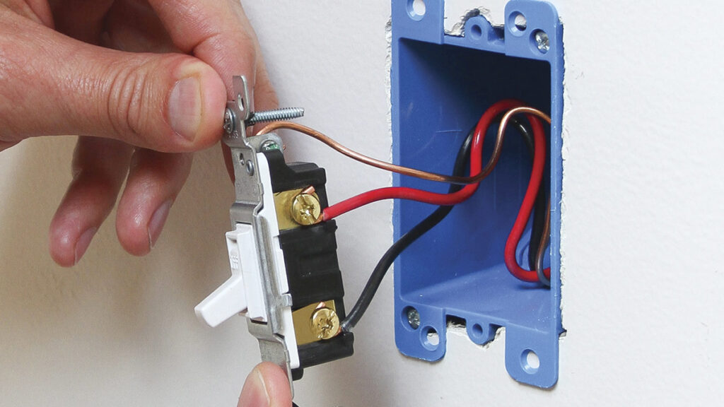
A simple lighting circuit has several conductor roles. Understanding those roles is more important than memorizing wire colors.
Line Wire
The line wire brings unswitched power from the electrical panel or another source.
It remains energized whenever the circuit breaker is on, whether the wall switch is on or off.
Line may also be called:
- Incoming hot
- Supply hot
- Permanent hot
- Feed wire
Load Wire
The load wire carries switched power from the wall switch to the light fixture.
It becomes energized when the switch is turned on. When the switch is turned off, the load wire should no longer supply power to the light.
Load may also be called:
- Switched hot
- Switch leg
- Outgoing hot
- Fixture feed
Neutral Wire
The neutral conductor completes the electrical path back toward the source.
In a typical single-pole circuit, neutral wires are connected together inside the switch box and do not attach to a basic mechanical switch.
Smart switches, timers, occupancy sensors, and other electronic devices may need a neutral connection to power their internal components.
Ground Wire
The equipment-grounding conductor provides a safer path for fault current.
It normally connects to:
- The switch’s green grounding screw
- A metal electrical box, when required
- The light fixture’s grounding lead or screw
- Other grounding conductors in the circuit
The ground wire should never be used as a neutral or hot conductor.
Common Light-Switch Wire Colors
Wire colors provide clues, but they do not guarantee a conductor’s function. Older wiring, switch loops, remodeling work, and incorrect previous repairs can create unexpected arrangements.
Always verify the actual function of each wire.
Black Wire
Black commonly identifies an ungrounded or hot conductor.
Depending on the circuit, a black wire may be:
- Incoming line power
- Switched power to a fixture
- A traveler in a multi-location circuit
- A feed continuing to another device
White Wire
White normally identifies a neutral conductor.
In a standard feed-at-switch arrangement, white wires usually remain connected together in the back of the box and bypass the mechanical switch.
However, a white wire may be used as a hot conductor in some older switch-loop layouts. When white is used as hot, it should be marked with black tape or another approved form of reidentification.
Never assume a white wire is safe to touch.
Red Wire
Red is another hot-conductor color.
It may be used as:
- A switched-hot wire
- A traveler in a three-way circuit
- A second controlled output
- An interconnection conductor
Its function depends on the circuit.
Bare Copper or Green Wire
Bare copper and green wires normally serve as equipment-grounding conductors.
They connect metal parts and electrical devices to the grounding system.
Other Colors
Blue, yellow, orange, and other colors may appear in conduit systems or more complex circuits.
These wires may identify:
- Travelers
- Switched legs
- Multiple circuits
- Control conductors
- Different voltage systems
Do not rely on general color rules when the wiring method is unfamiliar.
Types of Light Switches
Before disconnecting a switch, identify its type. A single-pole switch cannot always replace another switch that looks similar from the front.
Single-Pole Switch
A single-pole switch controls a light from one location.
It normally has:
- Two circuit terminals
- One ground terminal
- On and off markings on many models
Single-pole switches are common in bedrooms, bathrooms, closets, garages, and small rooms with one control location.
Three-Way Switch
A three-way switch allows one light to be controlled from two locations.
Common examples include:
- Both ends of a hallway
- The top and bottom of stairs
- Two entrances to a room
- A garage and an interior doorway
A three-way switch normally has:
- One common terminal
- Two traveler terminals
- One grounding terminal
The common terminal is often darker than the traveler terminals. The common wire must return to the common terminal when a switch is replaced.
Four-Way Switch
A four-way switch is used when one light is controlled from three or more locations.
A typical arrangement includes:
- One three-way switch at the first location
- One three-way switch at the final location
- One or more four-way switches between them
Four-way circuits contain multiple traveler connections and are more complicated than standard single-pole wiring.
Dimmer Switch
A dimmer adjusts the brightness of a light.
The dimmer must match:
- The light-bulb type
- The total electrical load
- Single-pole or multi-location operation
- The circuit voltage
- The fixture type
A dimmer made for incandescent lighting may not work correctly with LED bulbs. Incompatible products can cause flickering, buzzing, poor dimming, or shortened bulb life.
Smart Switch
A smart switch may offer:
- Mobile-app control
- Voice control
- Timers
- Schedules
- Remote operation
- Smart-home automation
Many smart switches require line, load, neutral, and ground connections. Some models are designed to work without a neutral, but their installation requirements vary.
Never use the ground conductor as a substitute for neutral.
Timer Switch
A timer switch turns a light or fan on and off at selected times.
Electronic timer switches often require a neutral conductor, although some models operate without one.
Motion-Sensor Switch
A motion or occupancy sensor turns lighting on when movement is detected.
These switches may require:
- Neutral wiring
- Grounding
- Minimum load
- Compatible lamps
- Specific placement in the room
Follow the instructions for the exact device.
Feed-at-Switch and Feed-at-Light Wiring
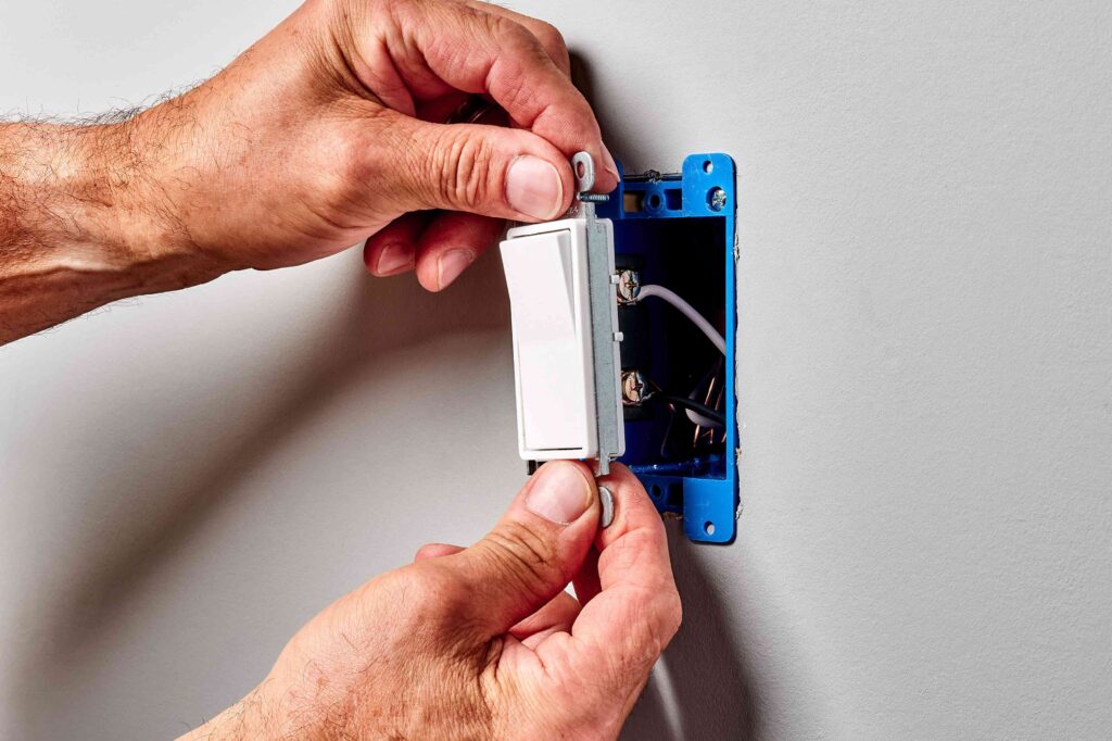
Power does not enter every lighting circuit at the same box. This difference affects what wires you will find behind the switch.
Feed-at-Switch Layout
In a feed-at-switch circuit:
- Power enters the wall-switch box.
- Incoming hot connects to the switch.
- Switched hot leaves the switch and travels to the fixture.
- Neutral wires are joined inside the switch box.
- Ground wires connect throughout the circuit.
This is the primary arrangement described in the step-by-step instructions below.
Feed-at-Light Layout
In a feed-at-light circuit, power enters the fixture box first.
A cable then carries power between the fixture box and the wall switch. Depending on the age and design of the circuit, the switch box may or may not contain a neutral conductor.
Traditional Switch Loop
In a traditional switch loop:
- Power enters at the light fixture.
- Unswitched hot travels from the fixture box to the wall switch.
- Switched power returns from the switch to the fixture.
Older switch loops often used a two-conductor cable. In some cases, the white wire carried hot power rather than serving as neutral.
This is one reason wire color alone should never be treated as proof of function.
Tools Needed to Wire a Light Switch
A basic switch replacement may require:
- Non-contact voltage tester
- Multimeter or two-pole voltage tester
- Flat-head screwdriver
- Phillips screwdriver
- Wire stripper
- Wire cutter
- Needle-nose pliers
- Flashlight
- Utility knife
- Approved wire connectors
- Electrical tape
- Replacement switch
- Matching faceplate
- Grounding pigtail, when needed
Use tools that are clean, dry, and in good condition.
A damaged tester or cracked screwdriver handle creates an unnecessary risk.
Materials for a New Light-Switch Circuit
New wiring may require:
- Approved electrical boxes
- Correctly sized electrical cable
- Cable clamps
- Cable staples
- Grounding screws
- Wire connectors
- Switch
- Faceplate
- Light fixture
- Mounting hardware
Installing a new circuit is more complicated than replacing an existing switch. New work may involve permits, inspections, cable-routing rules, box-fill calculations, drilling, fire blocking, and protection from physical damage.
Choosing the Correct Wire Size
The conductor size must match the circuit protection and installation requirements.
In many typical residential copper branch circuits:
- 14-gauge copper is used on 15-amp circuits.
- 12-gauge copper is used on 20-amp circuits.
These are common examples, not a substitute for checking the actual circuit, cable type, local code, and installation conditions.
Do not choose the conductor size only from the wattage of the light fixture. The wire must be suitable for the entire branch circuit and its breaker.
Never place undersized wire on a circuit protected by a breaker that allows more current than the wire can safely carry.
Safety Rules Before Wiring a Light Switch
Safety should come before every installation step.
Turn Off the Circuit Breaker
Locate the breaker that supplies the switch and light.
Turn the light on before switching off the breaker. When the light goes out, you have probably found the correct breaker, but that alone does not prove the entire box is safe.
Prevent Accidental Reconnection
Tell other people in the home that you are working on the circuit.
Label or secure the panel where practical so someone does not turn the breaker back on while the wires are exposed.
Test the Voltage Tester
Check the tester on a known live circuit before testing the switch box.
This confirms that the tester is working.
Remove the Faceplate and Test Again
After removing the faceplate, test:
- Every switch terminal
- Each insulated conductor
- Wire bundles inside the box
- Nearby devices in the same box
- Metal boxes or mounting straps
A multi-gang box can contain more than one electrical circuit.
Confirm the Tester Afterward
Test the device again on a known live source after checking the circuit.
This helps confirm it did not fail during the test.
Stop When the Wiring Looks Unsafe
Do not continue when you see:
- Melted insulation
- Burned terminals
- Blackened copper
- Cracked or brittle wires
- Water damage
- Aluminum branch-circuit wiring
- Uncovered splices
- Several unidentified circuits
- Missing electrical boxes
- Excessive heat
- A burning smell
- Severe overcrowding
These conditions require professional inspection.
How to Wire a Light Switch: Single-Pole Replacement
The following process covers a typical like-for-like replacement of an existing single-pole switch.
It assumes that:
- The light is controlled from one location.
- The old circuit worked correctly.
- The conductors are copper.
- The wiring and box are in good condition.
- You are not changing the circuit design.
Step 1: Select the Correct Switch
Choose a single-pole switch with the correct:
- Voltage rating
- Current rating
- Wiring compatibility
- Load compatibility
- Toggle or rocker style
Do not install a single-pole switch where a three-way switch is required.
Step 2: Turn Off and Verify the Power
Turn off the circuit breaker.
Use a voltage tester to confirm that the switch terminals and conductors are not energized.
Never rely only on the wall switch or breaker label.
Step 3: Remove the Faceplate
Unscrew the faceplate and inspect the area.
Look for:
- Cracks
- Discoloration
- Burn marks
- Melted plastic
- Unusual odors
Signs of overheating may indicate a loose connection or overloaded device.
Step 4: Remove the Switch From the Box
Remove the top and bottom mounting screws.
Pull the switch forward gently. Avoid touching bare terminals even after the circuit has been tested.
Do not disconnect any wires yet.
Step 5: Photograph the Existing Connections
Take clear pictures from several angles.
Photographs help preserve:
- Wire positions
- Terminal locations
- Ground connections
- Cable arrangement
- Jumper or pigtail locations
Label the wires when the arrangement is not obvious.
Step 6: Confirm the Switch Type
A typical single-pole switch has two circuit terminals plus ground.
A switch with three circuit terminals plus ground is probably a three-way switch.
If the device contains several attached wires, electronic components, or unusual terminals, check its label before proceeding.
Step 7: Disconnect the Old Switch
Loosen the terminal screws and remove the conductors.
If the wires use rear clamp terminals, release them according to the manufacturer’s instructions.
Do not pull the conductors with enough force to damage them.
Step 8: Inspect the Wires
Check each conductor for:
- Nicks
- Corrosion
- Burn marks
- Damaged insulation
- Loose strands
- Excessive stiffness
- Insufficient length
A damaged end may need to be trimmed and restripped, provided enough conductor remains in the box.
Step 9: Strip the Correct Amount of Insulation
Use the strip gauge printed on the switch or follow the manufacturer’s instructions.
Removing too little insulation may create a weak connection. Removing too much may leave unnecessary copper exposed.
Step 10: Connect the Ground Wire
Attach the bare copper or green ground conductor to the switch’s green screw.
When several grounds are present, join them with an approved connector and add a grounding pigtail to the switch.
A metal box may also require a grounding connection.
Step 11: Connect the Circuit Wires
Connect one circuit conductor to each brass terminal.
On a simple mechanical single-pole switch, the two brass terminals are often interchangeable. However, electronic switches, dimmers, smart switches, timers, illuminated switches, and sensors may have specific line and load terminals.
Follow the labels and instructions for the exact product.
Step 12: Tighten the Connections
For a side-screw connection, form a hook in the conductor and wrap it around the screw in the direction the screw tightens.
Tighten the terminal firmly without damaging the screw or conductor.
For approved clamp-style back wiring, insert the wire to the correct depth and tighten the clamp screw as directed.
Step 13: Perform a Tug Test
Pull each connected conductor gently.
A wire that moves or slides out is not secure.
Step 14: Inspect the Finished Connections
Make sure:
- No excessive bare copper is visible.
- Insulation is not trapped under terminals.
- Ground is secure.
- No conductor is damaged.
- Terminal screws are tight.
- Wire connectors are fully installed.
- Line and load connections match the device instructions.
Step 15: Fold the Wires Into the Box
Fold the conductors carefully into the box.
Avoid:
- Sharp bends
- Pinched insulation
- Pressure on wire connectors
- Ground wires touching exposed hot terminals
- Forcing the device into an undersized box
Place larger splices toward the back when possible.
Step 16: Mount the Switch
Position the switch straight in the box.
Install the mounting screws and tighten them evenly. Do not overtighten them and distort the mounting strap.
Step 17: Install the Faceplate
Attach the faceplate.
Tighten the screws only enough to hold it securely. Plastic faceplates can crack when overtightened.
Step 18: Restore Power and Test
Turn the breaker back on.
Operate the switch several times and confirm that:
- The light turns on and off.
- The switch does not buzz.
- The light does not flicker.
- The breaker remains on.
- No burning smell appears.
- The faceplate does not become unusually warm.
Turn off the breaker immediately if you notice sparking, strong heat, smoke, buzzing, or a burning odor.
How to Wire a New Feed-at-Switch Circuit
A new feed-at-switch circuit generally works as follows:
- One cable brings line, neutral, and ground into the switch box.
- Another cable runs from the switch box to the fixture.
- Incoming hot connects to one switch terminal.
- Switched hot connects to the other terminal.
- Neutral conductors are joined together.
- Ground conductors are connected together.
- A ground pigtail connects to the switch.
- Switched hot connects to the fixture’s hot lead.
- Neutral connects to the fixture’s neutral lead.
- Ground connects to the fixture’s grounding point.
This explains the electrical path, but new wiring involves more than joining conductors. The boxes, cable routes, conductor sizes, supports, clearances, and circuit protection must comply with applicable rules.
New-circuit installation is normally a job for a qualified electrician unless the person doing the work has suitable training and local authorization.
How Neutral Wires Are Connected
In a typical feed-at-switch circuit, the incoming neutral and fixture neutral are joined inside the switch box.
A standard mechanical single-pole switch does not normally connect to neutral.
Use a wire connector rated for:
- The conductor material
- Wire gauge
- Number of conductors
- Installation environment
After making the splice, perform a gentle tug test and place it carefully in the box.
Do not join neutrals from unrelated circuits.
How Ground Wires Are Connected
Grounding conductors should remain continuous throughout the circuit.
A switch-box ground bundle may contain:
- Ground from the incoming cable
- Ground going to the fixture
- Pigtail to the switch
- Connection to a metal box
Use approved grounding connectors or another listed method.
Do not rely on electrical tape, loose twisting, or contact with random metal parts.
How the Light Fixture Is Connected
At a typical light fixture:
- Switched hot connects to the fixture’s black or marked hot lead.
- Neutral connects to the fixture’s white lead.
- Ground connects to the green wire, grounding screw, or mounting strap.
Keep all splices inside an approved electrical box.
Follow the fixture instructions because some LED fixtures, ceiling fans, chandeliers, and combination units have additional connections.
The box must also be rated to support the fixture’s weight. Ceiling fans and heavy fixtures may require special support boxes.
How to Identify Line and Load Wires
Line is the conductor that receives constant power from the source.
Load is the conductor that carries switched power toward the light.
The safest method during a simple replacement is to label the wires before disconnecting the old working switch.
Identifying line with energized testing can expose the person doing the test to dangerous voltage. It should only be performed by someone trained to use suitable test equipment and procedures.
When a new electronic device has clearly marked line and load terminals, do not guess. Contact an electrician when the conductors cannot be positively identified.
What If Both Switch Wires Are Black?
Two black wires on a single-pole switch are common.
One may be incoming line, and the other may be switched load.
On many simple mechanical single-pole switches, reversing the two brass-terminal conductors does not change normal operation.
This does not necessarily apply to:
- Smart switches
- Timers
- Sensors
- Electronic switches
- Illuminated switches
- Dimmers
- Combination devices
These products may require line and load to connect to specific terminals.
How to Wire a Three-Way Light Switch
A three-way circuit controls one light from two locations.
It normally contains:
- Two three-way switches
- A common terminal on each switch
- Two traveler conductors
- Ground wires
- Incoming line power
- Switched power to the fixture
In one common layout:
- Incoming hot connects to the common terminal on the first switch.
- Two travelers run between the two switches.
- The second switch’s common terminal connects to the light.
- Neutral bypasses the mechanical switches and continues to the fixture.
- Grounding conductors connect throughout the circuit.
The cable between the switches often contains black, red, white, and ground conductors.
The most important replacement step is identifying the common wire before removing it from the old switch. Mark it with tape and connect it to the common terminal on the replacement switch.
Do not identify the common conductor by color alone. Identify it by the terminal on the existing switch.
Common Three-Way Switch Problems
A three-way circuit may not work correctly when:
- The common wire is connected to a traveler terminal.
- A traveler is loose.
- The wrong switch type was installed.
- Travelers from different cables were mixed.
- An incompatible smart companion was used.
- The wrong wiring diagram was followed.
Typical symptoms include:
- The light works from only one location.
- One switch works only when the other is in one position.
- The light never turns on.
- The breaker trips.
Three-way troubleshooting often requires careful circuit mapping.
How to Install a Dimmer Switch
Before installing a dimmer, confirm that:
- The light bulbs are dimmable.
- The dimmer supports the bulb technology.
- The dimmer can handle the connected load.
- It matches single-pole or multi-location operation.
- It is approved for the circuit voltage.
- It is not being used for a fan or motor unless specifically rated for that purpose.
Many dimmers use attached wire leads rather than screw terminals. Connect those leads with the approved wire connectors.
Dimmer capacity may be reduced when several devices share the same box, depending on the product design. Follow the manufacturer’s instructions.
How to Install a Smart Switch
Before buying a smart switch, inspect the circuit requirements.
A smart switch may need:
- Line
- Load
- Neutral
- Ground
- Traveler connections
- A compatible companion switch
- Enough space in the electrical box
- Supported Wi-Fi or smart-home technology
Many smart switches are deeper than standard mechanical switches. An older or crowded box may not have enough room.
Follow the exact wiring diagram supplied with the device. Different models from the same company may use different connection methods.
Can You Install a Smart Switch Without a Neutral?
Sometimes.
Possible solutions include:
- A smart switch designed for no-neutral installations
- Running a neutral conductor to the box
- Installing a compatible module at the fixture
- Using smart light bulbs
- Using a wireless remote-control system
Never use the ground conductor as neutral.
A no-neutral smart switch may also require compatible bulbs, a bypass device, or another accessory.
Electrical Box Size and Box Fill
Every electrical box has limited capacity.
Box-fill considerations include:
- Number of insulated conductors
- Conductor size
- Grounding wires
- Devices
- Internal clamps
- Splices
- Pigtails under applicable rules
An overcrowded electrical box can cause:
- Damaged insulation
- Loose connections
- Pressure on devices
- Difficult servicing
- Excessive heat
- Pinched wires
A larger smart switch or dimmer may not fit safely in a box that held a small mechanical switch.
Do not force the device into place.
Should You Wrap Electrical Tape Around a Switch?
Some installers wrap approved electrical tape around a switch body to cover exposed side-terminal screws.
This may provide extra protection in a metal or crowded electrical box.
However, tape does not correct:
- Loose terminal screws
- Excessive bare copper
- Incorrect wiring
- Missing grounding
- Damaged insulation
- Inadequate box size
Tape should never be treated as a substitute for proper installation.
Common Light-Switch Wiring Mistakes
Not Testing for Voltage
A breaker label may be wrong, or another circuit may enter the same box.
Always test before touching wires.
Disconnecting Wires Before Recording Their Positions
Take clear photographs and label conductors before removing them.
Assuming Every White Wire Is Neutral
A white conductor may be reidentified and used as hot in a switch loop.
Switching the Neutral Instead of the Hot
A standard wall switch should normally interrupt the hot conductor.
Using Ground as Neutral
Ground and neutral serve different purposes. They must not be used interchangeably.
Installing the Wrong Switch Type
A single-pole switch cannot correctly replace a three-way switch without redesigning the circuit.
Misplacing the Common Wire
On a three-way switch, the common wire must connect to the common terminal.
Leaving Loose Connections
Loose connections may cause:
- Flickering
- Buzzing
- Heat
- Arcing
- Device failure
- Fire risk
Exposing Too Much Bare Copper
Only strip the length required for the terminal or connector.
Placing Too Many Wires Under One Screw
Do not place more than one conductor under a terminal unless the device is listed for that use.
Using the Wrong Wire Connector
The connector must be approved for the number, size, and material of the conductors.
Overcrowding the Box
Do not force wires and devices into a box that is too small.
Ignoring Aluminum Wiring
Aluminum branch-circuit wiring requires compatible devices and approved connection methods. Do not connect it to a standard copper-only device.
Troubleshooting Light-Switch Problems
The Light Does Not Turn On
Possible causes include:
- Burned-out bulb
- Tripped breaker
- Tripped GFCI or AFCI protection
- Failed switch
- Loose terminal
- Loose neutral splice
- Incorrect line or load connection
- Failed fixture
- Failed LED driver
- Damaged cable
Check the bulb and breaker before reopening the switch box.
The Light Stays On
Possible causes include:
- The switch has been bypassed.
- Line and load were joined directly.
- The switch has failed internally.
- A smart switch is connected incorrectly.
- The fixture receives power from another circuit path.
Turn off the breaker before inspecting the wiring.
The Light Flickers
Flickering may result from:
- Loose bulb
- Loose switch connection
- Loose neutral
- Failing light fixture
- Incompatible dimmer
- Non-dimmable LED bulb
- Failing LED driver
- Damaged conductor
Flickering in several rooms may indicate a larger electrical problem.
The Switch Buzzes
Persistent buzzing may indicate:
- Loose wiring
- Arcing
- Failing switch contacts
- Excessive load
- Incompatible dimmer and bulb
- Electronic device failure
Turn off the circuit and correct the cause.
The Switch Feels Hot
Some electronic dimmers may feel slightly warm during normal use.
Strong heat, melting, discoloration, or a burning smell is not normal. Turn off the breaker and arrange professional inspection.
The Breaker Trips When the Light Turns On
Possible causes include:
- Short circuit
- Ground fault
- Pinched wire
- Incorrect connection
- Damaged fixture
- Bare wire touching a metal box
- Failed switch
- Overloaded circuit
Do not repeatedly reset a breaker that continues to trip.
The Switch Sparks
Visible sparks outside the device, crackling, smoke, burned plastic, or a burning smell indicate a serious problem.
Turn off the breaker and do not use the switch until it has been inspected.
A Three-Way Switch Works From Only One Location
This often occurs when:
- The common wire is on a traveler terminal.
- One traveler is disconnected.
- The wrong switch type is installed.
- Conductors were misidentified.
- Smart-switch components are incompatible.
When Should a Light Switch Be Replaced?
Replace or inspect a switch when it:
- Feels loose
- Works intermittently
- No longer clicks firmly
- Has cracked plastic
- Shows burn marks
- Buzzes
- Produces visible sparks
- Becomes hot
- Smells burned
- Fails to control the light
- Has corroded or damaged terminals
Replacing the switch will not solve a problem caused by the fixture, wiring, breaker, or another device.
When to Call a Licensed Electrician
Call an electrician when:
- You cannot identify the wires.
- The voltage test gives unexpected results.
- More than one circuit enters the box.
- The wiring is aluminum.
- Insulation is burned, melted, or brittle.
- No grounding conductor is present.
- The breaker trips repeatedly.
- The switch becomes hot.
- There is a burning smell.
- The box is damaged or overcrowded.
- New cable must be installed.
- A neutral must be added.
- You are changing the circuit layout.
- The work requires a permit or inspection.
- The circuit controls a motor, fan, or specialty equipment.
- The wiring does not match the manufacturer’s diagram.
Professional help is safer than experimenting with an unfamiliar circuit.
How Long Does It Take to Replace a Light Switch?
A simple like-for-like single-pole replacement may take less than an hour for someone familiar with basic electrical safety.
The project may take longer when:
- The breaker is difficult to identify.
- The box is crowded.
- Conductors are damaged.
- Line and load must be mapped.
- The circuit is three-way.
- The new device is larger.
- A smart switch needs setup.
- The wiring does not match the expected layout.
Work slowly and verify each connection.
How Much Does Light-Switch Installation Cost?
The total cost depends on:
- Switch type
- Product quality
- Local labor rates
- Wall-box condition
- Wiring repairs
- Permit requirements
- New cable installation
- Troubleshooting time
- Smart-home features
A basic mechanical switch usually costs much less than a smart switch, timer, occupancy sensor, or advanced dimmer.
Professional costs rise when the electrician must repair damaged wiring or modify the circuit.
Final Light-Switch Wiring Checklist
Before restoring power, confirm that:
- The correct switch type is installed.
- Line and load are connected as required.
- Grounding is complete.
- Neutral splices remain secure.
- Terminal screws are tight.
- Wire connectors pass a tug test.
- No excessive copper is exposed.
- No insulation is damaged.
- Wires are folded neatly.
- No conductor is pinched.
- The box is not overcrowded.
- The switch is firmly mounted.
- The faceplate is installed.
After restoring power, check for:
- Normal light operation
- Flickering
- Buzzing
- Excessive heat
- Burning odor
- Sparks
- Breaker trips
Turn the breaker off immediately if any unsafe symptom appears.
Frequently Asked Questions About How to Wire a Light Switch
Connect incoming hot power to one switch terminal and the switched-hot conductor going to the light to the other. Connect the ground wire to the green grounding screw. Neutral wires usually remain spliced together and bypass the mechanical switch.
On many basic mechanical single-pole switches, either black circuit wire can connect to either brass terminal. Smart switches, dimmers, timers, sensors, and electronic devices may have specific line and load terminals.
A standard mechanical single-pole switch usually does not require a neutral connection. Many smart switches and electronic controls do.
In a typical feed-at-switch circuit, white neutral wires are connected together in the back of the box. They do not normally attach to a mechanical switch.
The bare copper or green ground wire connects to the switch’s green grounding screw. It may also connect to a metal electrical box and continue to the light fixture.
Yes. A white conductor may be used as hot in some switch loops or special circuit arrangements. It should be properly reidentified, but older installations may not be marked correctly.
One black wire may bring constant hot power into the switch box, while the other carries switched power to the light.
A basic mechanical single-pole switch may still operate if the two brass-terminal conductors are reversed. Electronic switches may require line and load to connect exactly as labeled.
No. Ground and neutral have different safety functions and should never be used interchangeably.
Line is the conductor that remains energized when the breaker is on. Identifying it may require energized testing, which should only be performed by someone trained to use appropriate test equipment safely.
A red wire may be a three-way traveler, switched-hot conductor, or another ungrounded conductor. Its function depends on the circuit.
A single-pole switch controls a light from one location. A three-way system uses two switches to control the same light from two locations.
Not as a direct replacement. A three-way switch must be replaced with another compatible three-way switch unless the circuit is professionally redesigned.
A three-way switch normally has three circuit terminals plus a ground terminal. One circuit terminal is common, and the other two are travelers.
Possible causes include a loose terminal, loose neutral splice, failing bulb, incompatible dimmer, damaged fixture, or incorrect wiring.
Buzzing may result from a loose connection, internal switch damage, arcing, overload, or dimmer incompatibility.
Strong heat may indicate a loose connection, overload, failing device, or incompatible dimmer. Turn off the breaker and have the circuit inspected.
The circuit may contain a short circuit, ground fault, pinched wire, damaged fixture, or incorrect connection. Do not repeatedly reset the breaker.
Possibly. Check whether the box contains the line, load, neutral, and ground connections required by the smart switch. Some models work without a neutral, but their requirements vary.
No. Turn off the circuit breaker and verify that the conductors are de-energized before working.
Many typical 15-amp residential circuits use 14-gauge copper, while many 20-amp circuits use 12-gauge copper. The correct size depends on the breaker, conductor type, circuit design, installation conditions, and local electrical rules.
Electrical tape is sometimes used as extra protection over side-terminal screws, especially in crowded or metal boxes. It does not replace correct wiring, grounding, or box sizing.
A straightforward like-for-like single-pole replacement may be manageable for someone who understands electrical testing and safe connections. Damaged, aluminum, ungrounded, multi-circuit, or unfamiliar wiring should be handled by a licensed electrician.
Conclusion
Understanding how to wire a light switch begins with understanding the function of each conductor.
In a typical single-pole feed-at-switch circuit, incoming hot power connects to one switch terminal. Switched hot leaves from the other terminal and continues to the fixture. Neutral wires remain joined, while ground wires connect the switch, electrical box, and fixture as required.
However, not every home uses the same layout. Older switch loops may use a reidentified white wire as hot. Three-way circuits contain common and traveler wires. Smart switches may require neutral wiring. Dimmers must match the connected bulb and load.
Always disconnect the circuit, verify the absence of voltage, record the original wiring, use the correct replacement device, and follow the manufacturer’s instructions. Stop and call a licensed electrician when the conductors are damaged, confusing, or different from the expected arrangement.