
3 way light switch wiring allows one light, fan, or other approved fixture to be controlled from two different locations. For example, you can turn on a staircase light at the bottom and turn it off after reaching the top. The same system works well in hallways, bedrooms, garages, kitchens, and rooms with more than one entrance. Although the wiring may seem confusing at first, the circuit follows a simple idea: one switch receives power, two traveler wires connect the switches, and the second switch sends switched power to the light. However, electrical wiring can cause shock, fire, serious injury, or death when completed incorrectly. Therefore, always turn off the correct breaker, verify that the circuit is de-energized with an appropriate tester, follow local electrical rules, and hire a qualified electrician when the conductors or circuit layout are unclear.
What Is 3 Way Light Switch Wiring?
A three-way lighting circuit uses two special switches to control one electrical load from two locations. The term “three-way” does not mean that three switches are used. Instead, it describes the internal operation of the switch and its three current-carrying terminals. Each switch has one common terminal and two traveler terminals. A modern switch also has a separate grounding terminal. Together, the two switches create or interrupt an electrical path to the light. As a result, either switch can change the light from on to off or from off to on, regardless of the position of the other switch.
Where Three-Way Switches Are Commonly Used
Three-way switches are most useful in places where a single control point would be inconvenient or unsafe. A staircase often has one switch at the bottom and another at the top. A long hallway may have one switch at each end. In a bedroom, one control may sit near the door while another is located beside the bed. Large kitchens, living rooms, basements, attached garages, outdoor pathways, and rooms with two entrances may also use this system. The main benefit is convenience, but the circuit can also improve safety because people do not need to walk through a dark area to reach the only switch.
Quick Reference Guide to Three-Way Switch Parts
| Part | Common appearance | Purpose |
| Common terminal | Dark, black, or marked COM | Connects to incoming line power or the switched-hot wire leading to the light |
| Traveler terminal 1 | Brass-colored screw | Carries one possible electrical path between the switches |
| Traveler terminal 2 | Brass-colored screw | Carries the second possible path between the switches |
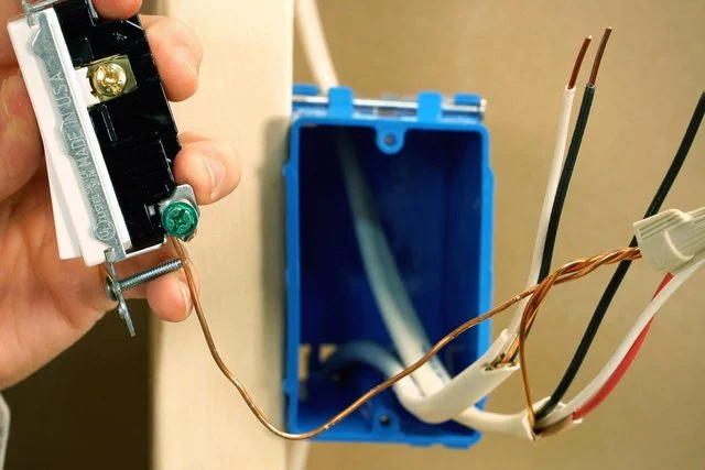
| Ground terminal | Green screw | Connects the switch to the equipment-grounding system |
| Toggle or rocker | Usually has no ON/OFF labels | Selects one traveler path or the other |
How a Three-Way Switch Works Internally
A standard three-way switch works as a single-pole, double-throw switch, commonly shortened to SPDT. The common terminal acts as the single pole, while the two traveler terminals provide two possible outputs. Inside the switch, the common contact connects to one traveler at a time. When the toggle is moved, the internal contact changes from one traveler to the other. The second switch works in the same way. If the two switches create a continuous route from incoming power to the fixture, the light turns on. If the selected paths do not connect, the light turns off. Flipping either switch changes the route and therefore changes the state of the light.
Why Three-Way Switches Have No ON and OFF Markings
A normal single-pole switch has a fixed ON position and a fixed OFF position. However, a three-way switch cannot determine the light’s condition by itself because the second switch also affects the circuit. A toggle pointing upward may turn the light on in one situation and off in another. Therefore, most mechanical three-way switches do not include ON and OFF labels. This absence of markings can help identify the switch, but checking the terminals is more reliable because some decorative or electronic controls also lack labels.
Understanding the Common Terminal
The common terminal is the most important connection on a three-way switch. On the line-side switch, it usually receives the incoming hot conductor from the electrical source. On the load-side switch, it normally connects to the switched-hot conductor leading to the fixture. The common screw is often darker than the traveler screws or marked COM. However, its physical position can vary between brands and models. It may be near the top on one switch and near the bottom on another. Therefore, never move conductors based only on screw position when replacing a switch. Instead, identify the wire connected to the old dark common screw and move it to the marked common terminal on the replacement device.
Understanding Traveler Wires
Two traveler conductors connect the two three-way switches. They provide the alternate paths that allow either switch to change the light’s condition. In many residential cables, red and black conductors serve as travelers. However, wire color does not guarantee function. Remodels, older wiring methods, conduit systems, and previous repairs may use different colors. A white conductor may also have been re-identified for use as an ungrounded conductor in certain older layouts. Therefore, travelers should be identified by circuit tracing, labels, terminal connections, approved testing, and the correct wiring diagram rather than color alone.
Does Traveler Order Matter?
On most ordinary mechanical three-way switches, the two traveler conductors are interchangeable with each other. One traveler can connect to either brass traveler screw without changing normal operation. However, the common conductor is not interchangeable with a traveler. When the common wire is placed on a traveler terminal, the circuit may work from only one location or may operate only when the second switch is in a certain position. Therefore, correct identification of the common conductor matters more than the order of the two travelers.
Line, Load, Neutral, and Ground Explained
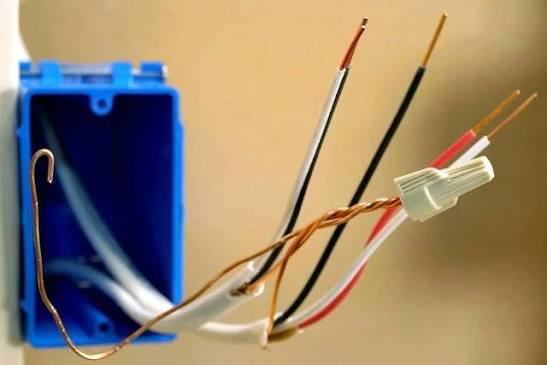
The line conductor brings unswitched power from the electrical source. The load conductor carries switched power from the final switch to the light fixture. The neutral conductor completes the normal electrical path from the fixture back toward the source. The equipment-grounding conductor provides a safety path if a fault energizes metal parts. These conductors serve different purposes and must not be treated as interchangeable. In particular, neutral should never be used as a substitute for equipment grounding, and a ground conductor should not carry normal operating current.
Does Neutral Connect to a Mechanical Three-Way Switch?
A traditional mechanical three-way switch normally does not connect directly to neutral. Instead, the neutral conductor continues to the light fixture, either directly or through splices in one or more boxes. However, neutral may still be present inside the switch box. Many smart switches, timers, occupancy sensors, and electronic dimmers need a neutral connection to power their internal electronics. Therefore, homeowners should not assume that every switch box contains a usable neutral. Before purchasing an electronic replacement, check the product’s exact wiring requirements and confirm which conductors are actually available.
Why Grounding Is Important
The equipment-grounding conductor normally carries no current during correct operation. However, it provides a low-resistance path if a fault causes voltage to reach a metal switch strap, electrical box, fixture, or other conductive part. This path helps the breaker or protective device operate quickly. Grounding conductors should remain continuous through the circuit and connect to each grounded switch, metal box, and fixture where required. A light may appear to work even when grounding is missing, but that does not make the installation safe.
The Most Common Three-Way Wiring Layout
A common layout brings incoming power into the first switch box. The incoming hot conductor connects to the first switch’s common terminal. A cable containing two traveler conductors then runs between the first and second switch boxes. At the second switch, the travelers connect to the two traveler terminals, while the common terminal connects to the switched-hot conductor leading to the light. Neutral continues from the electrical source to the fixture without connecting to the current-carrying terminals of the mechanical switches. Grounding conductors connect the switches, boxes, and fixture as required.
Wiring When Power Enters at the Light Fixture
In some installations, source power enters the fixture box before reaching either switch. In this arrangement, the circuit must carry unswitched power toward the switches, provide two traveler paths between them, and return switched power to the fixture. As a result, the wiring may look more complex than a layout where power enters the first switch box. Some older switch-loop arrangements may also use a re-identified white conductor as an ungrounded conductor. Therefore, never assume that every white wire is neutral or that every black wire is permanently hot.
Wiring When the Light Is Between the Switches
The fixture may sit physically between the two switch locations while the electrical logic remains the same. One common terminal still receives line power, two travelers still connect the switches, and the other common terminal still supplies switched power to the light. However, some traveler conductors may pass through the fixture box without connecting directly to the lamp. Therefore, physical order does not always reveal electrical function. A correct diagram must show what each conductor does rather than simply showing the order of boxes along a wall or ceiling.
Power and Load in the Same Switch Box
Some circuits bring both incoming power and the fixture cable into the same switch box. This layout may require extra conductors between switch locations so the circuit can carry two travelers and return the switched connection. It may also create more splices and increase electrical-box space requirements. Therefore, the wiring method must match the actual cable arrangement, device type, box size, and locally adopted electrical rules. A diagram for a different physical layout should not be copied simply because it also contains two three-way switches.
Common Cable Types Used in Three-Way Circuits
A typical North American residential installation may use a two-conductor cable with ground for line or load connections and a three-conductor cable with ground between the switches. For example, 14/2 and 14/3 copper NM-B cables often appear on properly protected 15-amp indoor lighting circuits. However, these cable types are not suitable for every installation. A 20-amp circuit commonly requires 12-gauge conductors. Outdoor, wet, underground, commercial, or conduit installations may require different wiring methods. Cable type, insulation, conductor size, breaker rating, device rating, and installation environment must all match.
14-Gauge Versus 12-Gauge Conductors
Fourteen-gauge copper conductors are commonly associated with 15-amp branch circuits. Twelve-gauge copper conductors are commonly used on 20-amp circuits. A general online diagram that shows 14/3 cable does not make 14-gauge wiring acceptable on every circuit. Never place undersized conductors on a larger breaker. In addition, switches must be rated for the circuit voltage, current, and load type. Fans, motors, LED drivers, fluorescent ballasts, and other loads may create requirements that differ from a simple incandescent lamp.
How to Identify an Existing Three-Way Switch
After power has been disconnected and verified off, a traditional three-way switch can often be identified by its terminals. It normally has one dark common screw, two lighter traveler screws, and one green ground screw. It also usually lacks ON and OFF markings. However, electronic switches, decorative controls, dimmers, and smart devices may use wire leads, removable connectors, special companion terminals, or electronic communication connections. When the device does not match a standard mechanical design, check the model number and manufacturer documentation.
Replacing an Existing Three-Way Switch
Before disconnecting an old switch, photograph the existing connections and label the wire attached to the dark common terminal. This step prevents one of the most common replacement mistakes. The new switch may place its common terminal in a different physical position, so conductors should not be transferred screw for screw based only on location. The identified common wire must connect to the new common terminal, the two travelers connect to the traveler terminals, and the grounding conductor connects to the green ground terminal. Strip length, terminal torque, and connection method should follow the instructions supplied with the device.
Safe Preparation Before Opening a Switch Box
Turn off the correct breaker before removing a wall plate or touching conductors. Next, verify the absence of voltage with a properly rated testing device. Do not rely only on a handwritten panel label, the position of the wall switch, or an assumption that one breaker controls the entire box. Multi-gang boxes may contain conductors supplied by more than one circuit. Shared circuits and incorrect panel labels can also create unexpected hazards. If any conductor remains energized or cannot be confidently identified, stop and contact a qualified electrician.
Tools Commonly Used for Switch Replacement
Typical tools may include a properly rated voltage tester, insulated screwdrivers, wire strippers, pliers, approved wire connectors, electrical labels, a flashlight, and the manufacturer’s instructions. However, owning these tools does not make live troubleshooting safe. Some electrical tests require specialized training, protective equipment, and a controlled procedure. In addition, the correct strip length and tightening torque vary by switch model. Always use the strip gauge and torque information provided by the manufacturer.
Conceptual Installation Process
A qualified installer begins by confirming that the switches, load, cable, conductor size, breaker, electrical boxes, and wiring method are compatible. Power is then turned off and the absence of voltage is verified. The installer identifies the line-side common, load-side common, two travelers, neutral path, and grounding path. Each conductor is connected according to the exact device instructions and a verified diagram that matches the physical layout. Afterward, all connections are inspected, conductors are folded carefully into the boxes, devices and wall plates are secured, power is restored, and both switch locations are tested. If the real wiring does not match the approved diagram, the installer should stop rather than improvise.
How to Test Correct Three-Way Operation
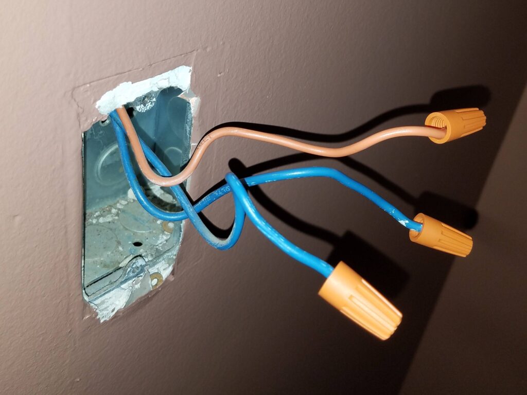
A correct circuit allows either switch to change the state of the light in every position of the other switch. Start with the light off and operate the first switch. Then operate the second switch. Continue until all four combinations of switch positions have been tested. The light should change state every time either switch is flipped. Do not use “both toggles up” or “both toggles down” as a universal test because switch mounting, traveler order, and physical orientation can vary.
Why One Switch Works Only in Certain Positions
When one switch controls the light only while the other switch remains in a particular position, a common conductor may have been placed on a traveler terminal. A loose traveler, defective switch, broken conductor, or poor splice may create a similar problem. Reversing the two travelers on a conventional mechanical switch usually does not cause this symptom because the travelers are normally interchangeable. Therefore, the first troubleshooting step is to verify the common-terminal connections after safely de-energizing the circuit.
Why the Light Does Not Turn On
A light that never turns on may have a failed lamp, tripped breaker, open neutral, disconnected line conductor, disconnected load conductor, loose common connection, broken traveler, defective switch, or failed fixture. Begin with simple checks, including the bulb and breaker, before opening electrical boxes. After the circuit has been turned off and verified de-energized, inspect for loose wires, heat damage, damaged insulation, poor splices, and incorrect terminal placement. Energized testing should be left to a qualified electrician.
Why the Light Stays On
A light that remains on may have been connected directly to unswitched line power instead of the switched output. An incorrect splice may also bypass the three-way switching path. Smart controls can remain on because of programming settings, wiring errors, minimum-load issues, incompatible lamps, or a failed electronic component. Therefore, compare the actual circuit with the exact instructions for the installed switches rather than relying on a generic mechanical-switch diagram.
Why a Switch Buzzes or Feels Hot
A standard mechanical switch should not produce loud buzzing, crackling, smoke, or a burnt smell. Some electronic dimmers may feel slightly warm during normal use, but excessive heat, discoloration, strong odor, or noise requires immediate attention. Turn off the circuit and stop using the switch. Possible causes include a loose connection, overloaded device, incompatible dimmer, poor terminal contact, damaged conductor, or failed internal component. An electrician should inspect the circuit before power is restored.
Common 3 Way Light Switch Wiring Mistakes
Common mistakes include placing the common wire on a traveler terminal, assuming terminal position is identical on every switch, trusting wire color without testing, disconnecting the ground, confusing neutral with a traveler, using the wrong cable size, installing incompatible dimmers, overcrowding the electrical box, and following a diagram that does not match the actual layout. Another frequent mistake is disconnecting every wire before labeling the common conductor. Careful photographs, labels, manufacturer instructions, and proper testing can prevent many of these problems.
Three-Way Switch Versus Single-Pole Switch
A single-pole switch controls a load from one location and usually has two current-carrying terminals plus ground. A three-way switch controls the same load as another three-way switch and has three current-carrying terminals plus ground. A normal single-pole switch cannot replace one member of a three-way pair while preserving two-location control. Although a mechanical three-way switch can sometimes function as a single-pole device when common and one traveler are used, it has no fixed ON and OFF markings. A correct single-pole switch is usually the clearer choice for a one-location circuit.
Three-Way Switch Versus Four-Way Switch
A three-way switch belongs at each end of a multi-location circuit. A four-way switch sits between the two end switches when the light must be controlled from three or more locations. Therefore, a three-location system normally uses two three-way switches and one four-way switch. A four-location system uses two three-way switches and two four-way switches. Additional four-way switches can be added between the end switches for more control points.
Using a Three-Way Dimmer
A three-way dimmer lets a light be controlled from two locations while brightness adjustment depends on the product design. Some systems use one dimmer and one compatible mechanical switch. Others use one master dimmer and a matching companion control. Two ordinary master dimmers generally cannot be installed together unless the manufacturer specifically supports that arrangement. Before installation, check lamp type, LED compatibility, minimum and maximum load, total wattage, and multi-location instructions.
Smart 3 Way Light Switch Wiring
Smart switches often use different connections from traditional mechanical devices. Some require line, load, neutral, ground, and a communication traveler. Others use one wired master switch and one companion device. Certain systems replace the second wired switch with a wireless remote. Therefore, there is no single smart three-way diagram that works for every brand or model. The exact product instructions must determine the connection method.
Can a Smart Switch Work Without Neutral?
Many smart switches require neutral because their electronics need continuous power. However, specially designed no-neutral models are available. These products may require a compatible hub, bridge, lamp type, ground connection, bypass device, or wireless companion. “No neutral required” does not mean that the switch can be connected randomly or that conductors can be repurposed without following the manufacturer’s diagram.
Can Two Smart Master Switches Control One Light?
Usually, two independent smart master switches cannot be connected to the same light in a traditional three-way arrangement. Many systems use one load-controlling master device and one or more compatible companion controls. Installing two incompatible masters may prevent operation or damage the devices. Therefore, buy switches that are listed by the manufacturer as a compatible multi-location set.
LED Lamps and Three-Way Circuits
Basic mechanical three-way switches usually work with approved LED loads within their ratings. However, electronic dimmers and smart switches require additional compatibility checks. An incompatible LED lamp may flicker, glow faintly when off, shut down unexpectedly, buzz, or fail to dim smoothly. Therefore, confirm that the control supports the lamp type and total wattage. When available, use the manufacturer’s compatible-lamp list.
Electrical Box Size and Box Fill
Three-way circuits often contain more conductors and splices than simple single-pole circuits. Smart switches and dimmers can also be deeper than mechanical switches. Therefore, the electrical box must provide enough space for all insulated conductors, grounding conductors, clamps, connectors, and devices. Overcrowding can damage insulation, loosen connections, and create excessive heat. If the existing box is too small, an approved larger box or extension may be needed.
Older Wiring and Special Conditions
Older homes may contain aluminum branch-circuit wiring, cloth-covered conductors, ungrounded boxes, knob-and-tube wiring, brittle insulation, shared neutrals, or undocumented alterations. Many modern switches are approved only for copper or copper-clad conductors unless clearly marked otherwise. Do not connect a copper-only device directly to aluminum wiring. These conditions require approved products, special connection methods, and professional evaluation.
When to Call an Electrician
Call a qualified electrician when conductors cannot be identified, more than one breaker supplies the box, insulation appears burned or brittle, aluminum wiring is present, the circuit lacks a dependable grounding path, the breaker trips repeatedly, or a switch becomes hot or noisy. Professional help is also appropriate when a smart switch requires neutral but none is available, when the wiring does not match the manufacturer’s diagram, or when local rules require permits and inspections.
Benefits of Three-Way Lighting Control
The main benefit is convenience because one light can be controlled from either end of a room, hallway, staircase, or outdoor path. The circuit can also improve safety by reducing the need to move through dark areas. In addition, users can turn lights off from the location where they leave a space, which may reduce unnecessary energy use. Smart and dimming controls can add scheduling, wireless companions, voice control, and adjustable brightness when they are installed according to approved instructions.
Frequently Asked Questions About 3 Way Light Switch Wiring
3 way light switch wiring is a circuit arrangement that allows one light or approved fixture to be controlled from two separate locations. It uses two three-way switches connected by two traveler conductors.
The name refers to the switch’s three current-carrying terminals: one common terminal and two traveler terminals. A separate ground terminal is also present on modern grounded switches.
A standard grounded three-way switch normally has three current-carrying connections and one grounding connection. The current-carrying connections include one common and two travelers.
The common screw is usually darker than the traveler screws or marked COM. However, its physical position varies between manufacturers.
The common conductor is often black, but color alone does not prove its function. It should be identified by terminal markings, labels, circuit tracing, and proper testing.
Travelers are the two conductors that connect the traveler terminals of the two three-way switches. Red and black are common colors, but other colors may be used.
On most conventional mechanical three-way switches, the two travelers can connect to either traveler terminal. However, the common conductor must connect to the common terminal.
Neutral normally does not connect to a basic mechanical three-way switch. However, many smart switches, timers, sensors, and electronic dimmers require neutral.
A white conductor may be neutral, or it may have been re-identified for use as an ungrounded conductor in an older switch loop. Its function must not be assumed from color alone.
A common conductor may have been connected to a traveler terminal. A loose traveler, failed switch, damaged conductor, or poor splice can cause a similar problem.
Possible causes include a failed lamp, tripped breaker, open neutral, loose common connection, broken traveler, defective switch, or failed fixture.
No, not while keeping normal control from two locations. A traditional two-location circuit requires a three-way switch at each end.
A mechanical three-way switch can sometimes operate as a single-pole device by using common and one traveler. However, it lacks fixed ON and OFF markings.
Use two three-way switches at the ends of the circuit and one four-way switch between them. Add more four-way switches for additional control locations.
Only when the selected products are designed to work together. Many systems require one master dimmer and one compatible companion or mechanical switch.
Many smart switches need neutral, although some no-neutral models are available. The exact requirements depend on the product.
No. It may be suitable for part of a properly protected 15-amp indoor residential circuit, but wire size and cable type must match the breaker, environment, load, and local electrical rules.
The light’s condition depends on both switches. Therefore, either toggle position can represent on or off at different times.
Not necessarily. Physical switch orientation and traveler arrangement can vary, so toggle position is not a reliable diagnostic method.
No. Colors are useful conventions, but they do not guarantee conductor function. Proper inspection, testing, labeling, and circuit tracing are required.
It may be manageable for someone who understands the circuit, can identify every conductor, has suitable testing equipment, and is permitted to complete the work. Otherwise, a qualified electrician should handle it.
Identify and label the common conductor before removing the old switch. Then connect it to the common terminal on the replacement switch rather than copying the old screw position.
Conclusion
3 way light switch wiring provides convenient control of one light or approved load from two locations. One switch’s common terminal connects to line power, the other switch’s common connects to the switched-hot conductor leading to the fixture, and two traveler wires provide alternate paths between them. Neutral normally continues to the light rather than connecting to the current-carrying terminals of ordinary mechanical switches, while grounding protects people and equipment during faults. Because real circuits can use different layouts, cable types, smart controls, dimmers, and older wiring methods, every installation must follow the exact device instructions and local electrical requirements. Always turn off power, verify the absence of voltage, identify conductors carefully, and hire an electrician whenever the circuit is uncertain.